Finite State Machines
There are two styles of finite state machine.
- Moore vs Mealy
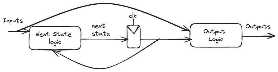
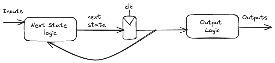
FSMs are modeled in Verilog with an always block defining the state registers and combinational logic defining the next state and output logic.
A comparison between Mealy and Moore FSMs, highlighting the differences in their characteristics and applications. For example:
| Moore FSM | Mealy FSM | |
|---|---|---|
| Output | Synchronized with clock | Not synchronized with clock |
| States | More states required for complex logic | Fewer states required for complex logic |
| Transitions | Only depend on current state | Depend on current state and inputs |
- FSM Verilog Template:
reg [state vars]
parameter [state encodings]

always @(posedge clk)
	case (state)
		[transitions]
	endcase

assign output = f(state);
FSM Example:
Divide-by-3 Counter
Let’s look at a simple finite state machine (FSM) example with one output and no inputs - a divide-by-3 counter. The output should be asserted (set to 1) every three clock cycles.
The state transition diagram for this Moore FSM is:
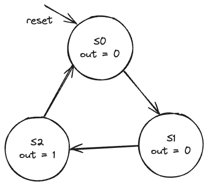 The output value is labeled in each state because in a Moore machine, the output depends only on the current state.
There are three states:
- S0
- S1
- S2
On each clock edge:
- S0 transitions to S1
- S1 transitions to S2
- S2 transitions to S0
Here is the Verilog code to implement this FSM:
module divideby3FSM(
	input clk,
	input reset,
	output out);

	// State Encoding
	reg [1:0] state, nextstate;

	parameter S0 = 2'b00;
	parameter S1 = 2'b01;
	parameter S2 = 2'b10;

	// State Registers
	always @(posedge clk, posedge reset)
		if (reset) state <= S0;
		else       state <= nextstate;

	// Next State Logic
	always @(*)
		case (state)
			S0: nextstate <= S1;
			S1: nextstate <= S2;
			S2: nextstate <= S0;
			default: nextstate <= S0;
		endcase

	// Output Logic
	assign out = (state == S2);
endmodule
The key components of the FSM are:
stateregister - holds the current statenextstatelogic - computes next stateoutputlogic - generates outputs based on current state
By breaking the FSM into these three sections, we can clearly see the state transitions, outputs, and combinational/sequential logic.
Clock Divider
Let’s look at an example of a clock divider module in Verilog. This module takes in a clock signal CLK and generates an output clock CLK_DIV3 that is a third of the input frequency.
The module interface is:
input CLK        // Input clock
input RESET      // Active-high reset
input CE         // Clock enable
output CLK_DIV3  // Divided clock outputs
The implementation uses a 2-bit counter count to divide the frequency by 3.
module clk_div3 (
  input CLK,
  input RESET,
  input CE,
  output CLK_DIV3
);

reg [1:0] count; // Counter to divide clock by 3
reg CLK_DIV3;

always @(posedge CLK or posedge RESET) begin

  if(RESET) begin  // Asynchronous reset
    count <= 0;
    CLK_DIV3 <= 0;
  end

  else begin
    if(CE) begin  // Increment counter if CE is high
      count <= count + 1;

      if(count == 2) begin // When count reaches 2
        count <= 0;  // Reset counter
        CLK_DIV3 <= ~CLK_DIV3;  // Toggle output to divide clock
      end
    end
  end
end

endmodule
On each clock edge, the count value increments if CE is high. When count reaches 2, it resets to 0 and CLK_DIV3 is toggled to create a divided clock output.
The key advantage of this approach is that the divided clock rate can be easily configured by changing the counter size and toggle value.
We use an asynchronous reset rather than a synchronous reset for the following reasons:
NOTE
- It initializes the circuit immediately, regardless of clock edge:
An async reset allows the state to initialize as soon as
RESETis asserted high. This resets the circuit right away.With a sync reset, we would have to wait for a clock edge for the reset to take effect after asserting the signal.
- It handles issues with the clock:
If the clock signal is unstable during power up, an async reset will still reset the state reliably.
A sync reset would not work correctly if the clock is not toggling when reset is first applied.
- It resets sequencing logic cleanly:
- Any counters or state machines initialize to their first state. With a sync reset, intermediate states could be seen before resetting to initial state.